There have been a lot of conversations around IoT lately. As someone who has done his major in accounting and as someone who builds business and financial applications for a living, I had a lot of excitement and some reservations about starting on my IoT journey. I mean I am just a regular nerd without any electronics background. Should I be playing with Microcontrollers and live current? After a few weeks, I’m happy to announce that the journey has been fun and I think it has been a journey worth sharing with you.
The basic underlying idea is to control things over the internet and hence the need for a programmable chip or a microcontroller - a small tiny independent board with a programmable chip that can run code in an infinite loop. The code controls the chip and the chip controls the devices or things it is connected to.
The “control” in the microcontroller can be as simple as turning a LED on / off or something as complex as building a smart home, with lights, fans, entertainment systems and water pumps controlled using your code.
Most articles and you-tube IoT examples out there are either way too complex involving complex circuits and code, or way too simplistic and impractical where someone shows you how to make a LED blink with your code; which fortunately is a good start; but unfortunately does not allow you to anything practical with your microcontroller, which then puts your micro-controller in the same category as your gym membership - something you own but don’t actually use.
My goal with this series of posts, is to get started on IoT and provide enough insight on the topic to enable you to build something real and practical with it. The goal is also to take you to a point where IoT goes from yet another buzzword that electronics guys should be concerned about, to a practical, real, affordable and simple tool that you can use to build useful projects with.
In the first post we’ll cover some very basic concepts around the Arduino chipset (which is the micro-controller we are going to use for our IoT experiments) and write some basic code that runs on the chipset.
In the posts that follow we will attach some interesting modules to Arduino and write code to control these modules. Going ahead, we’ll get these modules and the microcontroller connected to your home Wifi and we’ll show you how you can control the microcontroller (and the modules connected to it) over the internet; and we’ll finally move on to working with real live electrical devices like, light bulbs and fans and control those with code.
All circuits we build in the process will be open sourced. All code we write in this process will also be on open sourced and will be posted here on this blog for you to use.
When I started with my IoT journey a few weeks ago, I knew nothing about physics (or electronics) other than some basics I had picked up in high school, most of which I had never paid any attention to or had forgotten over time. Long story short, I’m just a regular nerd who writes business applications / CRUD screens for a living and hence the series of these posts doesn’t require you to know physics or electronics to start. You will need to go out and buy a couple of cheap gadgets if you want to try some of these examples yourself but your overall investment will be less than 25 dollars.
And as a final disclaimer, I have never officially studied electronics so everything I write about here, is just a regular nerd trying to connect wires and have some fun. If something explodes (or if you cook a chipset or two) the responsibility is all yours!
Sounds good? Let's begin.
To start playing around with IoT we’re going to write code that controls devices so you’ll have to shell out some money and buy some basic devices. Even though there are platforms like the raspberry pi which make IoT much simpler, let’s start with buying a much cheaper micro controller which actually gets you a deeper understanding of the circuits you will be making, will make a smaller hole in your pocket and will help you stay away from having to run and entire Linux clone on your microprocessor like Raspberry Pi does.
Here are a few things you may want to go out and buy if you want to follow along:
- An Arduino UNO chipset - You can buy the original one or a cheap clone. I got one from amazon at about 7$.
- A Breadboard - so that you can connect wires and devices together without needing soldering equipment. I got mine from amazon at about 2$.
- Some jumper wires - so that you can connect devices on your Arduino and your breadboard. I picked up a neat set of male-to-male, male-to-female and female-to-female at Amazon. Cost of the whole kit? About 2$.
- A Few LEDs (and a few resistors) - which is the very first thing we will control with our code. You can also grab some resistors at 150 for just 1$ and a few LEDs for 3$.
- An ultrasonic transmitter - we will not be using it in the first demo, but we will need this in the third post, so it may be a good idea to get everything you will need in one shot. I picked up mine at 2$.
- A Wi-Fi module - that will eventually let you get connected to the internet over your home Wi-Fi connection and let you control the Arduino over an internet connection. Price? About 3$. Again, not something we will use in the first post, but something that we will use pretty soon.
- A Relay - that will let us control real live current / devices using our Arduino - we’re not going to use this for the next couple of posts but at 2$ a piece it’s something you may also want to order along with everything else mentioned above.
In under 25$ you have all you need to work on some meaningful IOT experiments and try out a few things.
We’ll get started with Arduino itself in this post and make it control a basic on-board LED light before we do some more interesting things with it. I do realize this example is highly non-practical but it is really simple, gets you used to the Arduino IDE and gets you familiar with the environment. So, let’s get started by making a LED blink, but before that lets begin by knowing our Microcontroller.
You can read article after after to understand the Arduino, but to start messing around with it, all you need to know is that is has 2 power output pins (using which connected devices can draw power) - one is a 3.3V power output pin, the other a 5V power output pin. Apart from the power pins it also has ground pins labelled “GND” and all circuits that you make will usually end / complete with the ground pin. Put simply, your wiring will start with the power pin and end in the ground pin, and you will control everything else that’s in between (i.e. everything that’s connected to your IO pins).
Depending on the device you are connecting to your Arduino you can decide the power output you want to use. Most devices will have specs which will tell you how much power they expect. Exercise some common sense when you pick the power pin - for example, don’t connect your jumper wire to a 5V pin when the device you are connecting expects 3.3V - if you do there is a high chance you will cook your device.
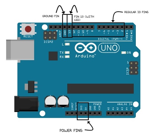
Apart from the two power pins there are also some digital pins where you write a high or a low. Think of writing a “high” as turning a switch on and think of writing a “low” signal as turning the switch off. Out of all these pins, pin 13 is special because it has an in-built LED (light) attached to it that you can control with your code.
To write code we’re going to get the Arduino studio, which you can download from here and install using a simple installer. Once done, you connect your Arduino to the USB port of your laptop (which is one of the sources from which Arduino gets it’s power). Of course Arduino itself, can also work without a machine and you can hook it up with a battery or direct power, but for now since we will be uploading our code from our machine to the chip, it makes sense to have it connected with our laptop using the USB port.
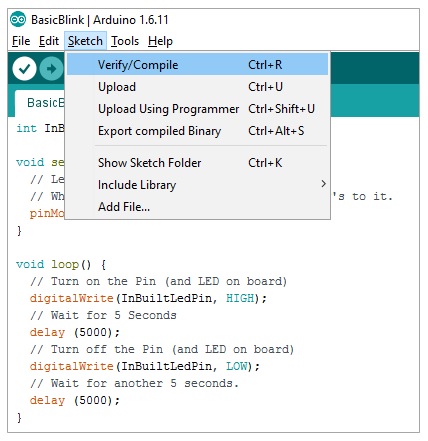
Once connected go to your Arduino studio and pick the right port your Arduino is connected to. Usually the IDE automatically detects this but if it doesn’t you can try different ports and try to upload your code on each one till it succeeds. All code that typically runs on the microcontroller is referred to as a sketch and each sketch has a loop, which keeps on running as soon as the sketch is uploaded and the microcontroller is powered on.
An empty sketch looks like this.
![]()
Setup function is where you write code that runs only once. Anything you write in in “loop” runs in an infinite loop while the microcontroller is powered and on.
Now it’s time to connect the dots and assemble everything we’ve read thus far. Remember when we were talking about writing highs (which is same as turning the pin on) and lows(which is same as turning the pin off)? We know pin 13 has an in-built LED (light) and if we can write a high to pin 13, it should turn the switch on and the LED should glow. If we then write a low to the same pin the LED should shut off. If we do that in a loop function and wait 5 seconds between the on and the off, we should have an LED that keeps on blinking every five seconds the moment you power on the microcontroller. Simple enough? That’s exactly what we are doing in the code below:
int InBuiltLedPin = 13;

void setup() {
  // Let's set Pin 13 as Output Pin
  // Which means we will write high's and low's to it.
  pinMode(InBuiltLedPin, OUTPUT);
}

void loop() {
  // Turn on the Pin (and LED on board)
  digitalWrite(InBuiltLedPin, HIGH);
  // Wait for 5 Seconds
  delay (5000);
  // Turn off the Pin (and LED on board)
  digitalWrite(InBuiltLedPin, LOW);
  // Wait for another 5 seconds.
  delay (5000);
}
Verify your sketch (which is the same as compiling your code):
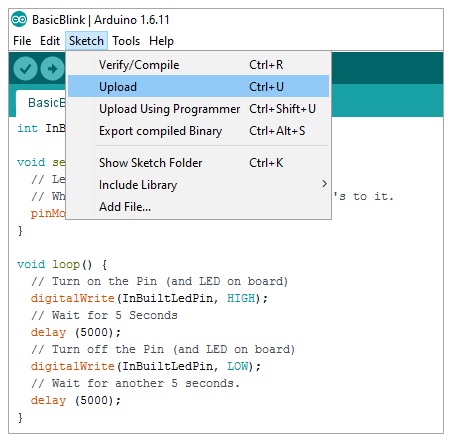
And once verified, upload your sketch on your Microcontroller:
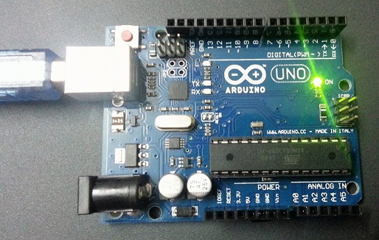
And if all has gone fine you should see your Microcontroller LED blink on in five seconds (notice the Red LED next to pin 13 light up in the below picture):
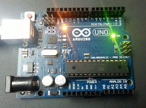
And off in another five seconds:
Of course, this will continue in a loop till you switch off the microcontroller by pulling the USB cable off, or till you upload a new sketch.
And with that, you have just controlled an onboard LED with your code. In the next post, we will attach an external LED to the Arduino using a breadboard and try and change the same code slightly to make that LED blink. If you’ve never worked on electronics before the next post will introduce you to a lot of basic concepts like breadboards and resistors. And from there we’ll be ready to build some real life projects. So stay tuned for the next post.
Comments are closed.